Mastering the Building Automation System Architecture for Efficiency and Scalability
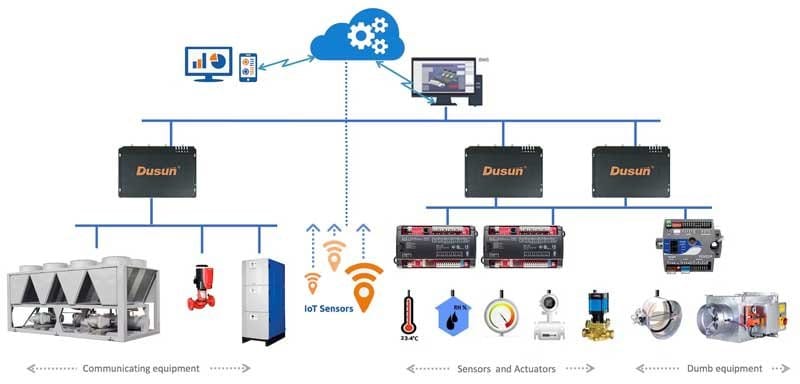
The architecture of building automation system represents the foundational framework that enables modern buildings to operate intelligently, efficiently, and responsively. This architecture is not only about how various elements are linked with others. It’s also about how such systems form a unified ecosystem to deal with HVAC systems as well as security methodology. For professionals tasked with specifying, designing, or maintaining these systems, a deep understanding of building automation system architecture is essential for delivering solutions that meet both current needs and future expansion requirements. The modern commercial and industrial plants require not a simple environmental control. They require sophisticated building automation systems and services that can adapt to changing occupancy patterns, optimize energy consumption in real-time, and provide actionable data for facility management decisions. The architecture of building automation system design has evolved significantly, incorporating network technologies, open protocols, and cloud connectivity that transform buildings into intelligent assets rather than static structures. Understanding the Foundational Layers of Building Automation System Architecture The architecture of building automation system design operates on multiple interconnected layers, each serving distinct functions while contributing to the overall system performance. Fundamentally, this architecture is similar to a pyramid with field-level devices at the bottom, followed by controllers, network infrastructure, and finally, the management interface with operators provided an interface with the whole system. The field level represents the most fundamental layer in the architecture of building automation system. This consists of sensors, actuators, and end devices that physically interact with building systems. The systems measure temperature, humidity, pressure, occupancy, and other parameters that operate dampers, valves, motors and switches. The cleverness of the current field devices has escalated exponentially and most of them have local processing facilities that reduce the load on the network and enhance the response time. Network infrastructure forms the circulatory system within the architecture of building automation system, enabling communication between all components. Modern implementations typically employ a combination of wired and wireless protocols, with Ethernet-based networks becoming increasingly prevalent at the supervisory level. BACnet, Modbus, and LonWorks remain industry standards, though proprietary protocols from manufacturers like Trane building automation system solutions continue to coexist within many installations. The network architecture should be in a way that supports the bandwidth, provide Components of Building Automation System: The Building Blocks Understanding the components of building automation system architecture requires examining each element’s role and how they interconnect to create functional intelligence. Controllers are the level of decision making, which takes data input through sensors and the control logic to control outputs. These range from application-specific controllers dedicated to single tasks like fan coil unit control to more sophisticated programmable controllers capable of managing multiple systems simultaneously. The supervisory layer within the architecture of building automation system provides centralized monitoring and management capabilities. With workstations with specialized software, the operator is able to see the performance of the system and reach setpoints, schedules and alarm responses. Modern interfaces incorporate dashboards that present complex data through intuitive graphics, making it easier for facility managers to identify trends and anomalies that might indicate equipment problems or optimization opportunities. Data management and storage infrastructure has become increasingly important in contemporary building automation system architecture. The analysis of energy, predictive maintenance, and performance benchmarking is possible through historical data collection. On-demand storage services are popular now. They have an extremely large capacity and you can access them from anywhere so long as you have internet access. This evolution supports the integration of IoT building automation system concepts, where traditional building systems converge with enterprise IT infrastructure to create truly smart buildings. Integration Strategies Within Building Automation System Architecture The architecture of building automation system implementation must account for integration with both building systems and enterprise networks. HVAC systems typically receive priority in automation strategies, but lighting control, access security, fire safety, and power monitoring all benefit from inclusion in the overall architecture. Open protocol adoption facilitates integration by enabling equipment from different manufacturers to communicate effectively, reducing vendor lock-in and providing flexibility for future modifications. Building automation for landlords and property management companies requires architecture that supports multi-tenant scenarios. It will entail the capacity of partitioning systems, to ascertain utility expenses, and to give tenants proper access to controls which impact their spaces along with the preservation of the integrity of building wide systems. The architecture of building automation system in commercial real estate must balance individual comfort preferences with overall building efficiency objectives. Enterprise system integration extends the building automation system architecture beyond traditional boundaries. The work order generation is streamlined through links to computerized maintenance management systems in case of equipment faults. Demonstration The systems can integrate with energy management systems to participate in demand response and reduce utility costs. Utility information is forwarded to the financial systems to properly track the budget and bill tenants. These links make building automation a tool that operates independently to a one that is an operational tool that helps in achieving organizational goals. Building Automation System Installation: Architectural Considerations Proper building automation system installation begins with architecture design that considers both current requirements and future growth. Physical infrastructure planning determines where to locate controllers, how to power devices, and what cable to utilize. Modern installations increasingly rely on wireless sensors and battery-powered devices to reduce installation costs and improve flexibility, but the core network backbone still requires careful physical planning. The architecture of building automation system must account for system scalability. The capacity of controllers, network bandwidth, and server processing speed ought to be in line with the expected growth without having to change it wholesale. This long-term mindset avoids the frequent situation in which effective initial implementations are curtailed by architecture constraints in situations where the people owning them desire to proceed with automation to other regions or systems. Commissioning represents a critical phase in building automation system installation, verifying that the implemented architecture performs as designed. This process inspections communication channels, verifies control programmes, calibers sensors and records system setup. Thorough commissioning prevents the operational
Why Your Facility Needs Integrated Industrial Control & Automation

Modern manufacturing demands precision, efficiency, and reliability. However, in most facilities, there is a problem of the outdated systems and disintegrated processes. Industrial control & automation addresses these challenges head-on. It changes the ways that facilities are run that save money and enhance quality of output. This technology is not only good, but it is becoming a requirement of competitive advantage. The modern world of industries demands to be integrated to facilitate solutions that are flexible. Understanding control and automation fundamentals helps facilities make informed decisions. Understanding Industrial Control & Automation Systems Industrial controls and automation combines hardware and software to manage facility operations. These systems monitor, control, and optimize manufacturing processes automatically. Sensors collect real-time data from equipment and production lines. Controllers process this information and make instantaneous adjustments. The outcome is a smooth running that minimally involves human intervention. Core Components of Automation Systems Every effective control system automation includes several critical elements. The brain of the system is the Programmable Logic Controllers (PLCs). They carry out control algorithms and communicate among field devices. Human-Machine Interfaces (HMIs) provide visual feedback to the operator. The SCADA systems collect data on various points and make them centrally monitored. Variable Frequency Drives (VFDs) have the advantage of controlling the speed of the motor. Combined these elements form a unified working system. Types of Control Systems Different facilities require different approaches to industrial process control and automation system implementation. Embarkation systems control singly and individual machines and processes. Continuous process control deals with such operations as chemical mixing or refining. Production is controlled in batches of production. Sequential control involves control that takes processes through pre-defined procedures. All the types have their industrial needs. Benefits of Integrated Industrial Control & Automation Implementing comprehensive industrial control & automation delivers measurable advantages. First, operational efficiency increases dramatically across all departments. Energy consumption drops as systems optimize resource usage continuously. Product quality improves through consistent, repeatable processes. Labor costs decrease while worker safety significantly improves. Equipment lifespan extends through predictive maintenance capabilities. 1. Enhanced Production Efficiency Control and automation systems eliminate bottlenecks in production workflows. Machines operate at optimal speeds without manual adjustment. Downtime reduces as systems detect problems before failures occur. Production schedules adapt automatically to changing demands. Real-time monitoring identifies inefficiencies for immediate correction. These improvements translate directly to bottom-line results. 2. Improved Safety Standards The most important thing in an industrial setting nowadays is safety. Industrial controls and automation minimize human exposure to hazardous conditions. The systems automatically shut down on sensing hazardous situations. Access controls prevent unauthorized personnel from dangerous areas. Emergency protocols execute instantly without human decision delays. The logging will be thorough and will give safety records. 3. Cost Reduction Strategies Financial benefits of control system automation extend beyond obvious savings. The energy management systems save 20-30% of utility costs. Reduction of waste generated by the accurate control decreases the cost of materials. The maintenance becomes proactive and not reactive, preventing expensive breakdown. The optimization of labor enables re-deployment of the staff to the value-adding activities. Key Technologies in Modern Industrial Control & Automation Today’s industrial control & automation leverages cutting-edge technological innovations. IoT sensors offer more details on data than ever. Artificial intelligence extracts patterns that can not be determined by people easily. Cloud computing is able to monitor or control remotely. Edge computing processes data nearer to responding to data. Such technologies are in collaborative systems. 1. Industrial Internet of Things (IIoT) IIoT transforms traditional industrial process control and automation system architectures. These interconnected devices interact across networks without human intervention. Machine-to-machine communication enables autonomous decision-making processes. Predictive analytics predict the failures of equipment weeks prior to their occurrence. Remote diagnostics implies that the visits of technicians to the site would be fewer. The continuous improvement is driven by data-driven insights. 2. Programmable Logic Controllers PLCs remain the backbone of most control and automation implementations. Modern PLCs offer processing power comparable to desktop computers. They handle complex algorithms while maintaining robust reliability. Programming has become more intuitive with graphical interfaces. Network connectivity allows integration with enterprise systems seamlessly. Their versatility makes them suitable for diverse applications. 3. SCADA Systems Supervisory Control and Data Acquisition enhances industrial controls and automation oversight. SCADA gives one a centralized view of various locations of facilities. Single workstations have thousands of data points monitored by its operators. The analysis of the historical data is used to outline the long-term tendencies. Alarm management provides a rapid reaction to the essential situation. It allows data-driven strategic planning when it is integrated with business systems. Industrial Control & Automation Implementation Strategies for Facilities Successful control system automation requires careful planning and execution. Start with an examination of the existing operations. Privatise areas of pain and areas of improvement. Create timetables of gradual implementation so as to reduce disruption in operations. Select chooses technology partners who are of experience in the industry. Make sure that staff training is adequate on all levels. Assessment and Planning Every industrial control & automation project starts with thorough evaluation. Document control systems, equipment, and existing processes in totality. objectively compare benchmark performance rates with industry standards. Involve operations, maintenance, and management team stakeholders. Create specific goals and objectives to be measured in terms of success. This foundation will create congruence among business and technology objectives. System Design Considerations Effective control and automation design balances multiple competing factors. Scalability guarantees that systems are expanded as new facilities are required. Redundancy will avoid single points of failure of critical systems. The level of cybersecurity protection is in place against even more advanced threats. Easy to use interfaces minimize training and errors. The standardisation eases the maintenance control, spares part inventory is minimised. Integration with Legacy Systems Most facilities face challenges integrating new industrial controls and automation technology. Older equipment does not always have new communication features. Protocol converters are used to mediate between old systems and new systems. Gradual replacement procedures retain continuity of production during transitions. With proper planning, there
High-Impact Industrial Automation Applications for Modern Machinery
Industrial automation applications have become the backbone of competitive manufacturing operations worldwide. These advanced systems combine both the hardware and the software to streamline the production processes. The modern day vendors require solutions that will give quantifiable efficiency returns. Modern machinery and industrial automation work together seamlessly to drive productivity. The change is ongoing because of the speedy technological development. Corporations that invest in these systems reap great benefits of competitive advantages. Industrial automation applications span diverse sectors from automotive to pharmaceuticals. Every industry demands specific solutions to unique demands of the operation. Indeed, integration of sensors, controllers and actuators forms intelligent ecosystems. The ecosystems react to real time information in real time. Efficiency in manufacturing is augmented by the automation systems being at their optimal operation level. Core Technologies Driving Industrial Automation 1. Programmable Logic Controllers in Manufacturing PLC factory automation represents the foundation of modern industrial control systems. These are rough digital computers that manage production processes in an efficient manner. PLCs run logic-based instructions controlling motors, valves and sensors. They have a rapid reprogramming flexibility to match other production needs. The old players at the industry enjoy PLCs due to their reliability. PLC factory automation systems have a modular expandable architecture. The manufacturers are in a position to scale without having to overhaul the systems. Real-time processing facilities guarantee real time responses to the production variables. This flexibility reduces wastage and maximization of resource base. The technology of automation industrial PLC is also improving each time with the new capabilities. 2. Plant Automation Software Solutions Plant automation software orchestrates complex manufacturing operations from centralized platforms. These are highly advanced systems that merge the various production lines. Data visualization tools avail actionable data in real-time to the operator. This information is used by decision-makers to maximize production strategies. The upper layer is the software that converts raw sensor data to business knowledge. Modern plant automation software incorporates artificial intelligence and machine learning algorithms. Unexpected failures in equipment are minimized by predictive maintenance functions. Scheduling modules of production are used to balance the workload among the available resources. Enterprise resource planning systems combined with their integration make business smoother. This total quality management system gives high productivity on operations. High-Impact Industrial Automation Applications Transforming Modern Machinery 1. Robotic Process Automation Industrial automation applications in robotics revolutionize repetitive manufacturing tasks. Collaborative robots are used in the safe and effective collaboration with human operators. Such systems deal with material handling, precision assembly and welding. The flexibility of the programming enables the rapid adjustment to the new design of products. Leadership producers gain a uniform quality and save a lot of money on labor. With the advanced vision systems, robots are able to detect and categorize the bits correctly. Force-sensing technologies support delicate operations to prevent damage. Complex workflow coordinating systems network robot armies together. Such coordination removes production line bottlenecks. Robotic automation has a persuasive payback. 2. Motion Control and Drive Systems Variable frequency drives optimize motor performance across machinery and industrial automation environments. These systems regulate the speed of the motor to an exact level according to the needs in production. Intelligent speed control results in large-scale reduction of energy consumption. Drive systems are being linked to automation industrial PLC networks to allow coordinated machines. High accuracy of motion control provides the quality of the product to the specifications. Servo motors offer high accuracy of positioning critical production. Examples are CNC machine, packaging, and material handling equipment. The control mechanisms of the feedback constantly readjust to the positional accuracy. The accuracy of this no longer needs defects and additionally minimizes waste of materials. New drive technology provides efficiency which was only a dream before. 3. Process Control and Monitoring Industrial automation applications for process control maintain optimal operating parameters continuously. Temperature, pressure, flow, and level sensors provide constant feedback. Control algorithms automatically adjust process variables to the desired setpoints. Such automation excludes human error in important functions of control. Automated process control results in a massive increase in product consistency. The control of operations within a plant is controlled centrally, with the distribution of control systems. Uncomplicated interfaces enable operators to view hundreds of process variables at a time. Alarm systems provide instant notification of the personnel on abnormal conditions. Trending of historical data determines opportunities of process optimization. These abilities revolutionize the work of plants. Industrial Automation Applications Integration Strategies for Maximum Impact Seamless System Architecture Successful industrial automation applications require careful planning of system architecture. The protocols adopted in communication should have good reliability in data transfer among equipment. Standardized interfaces like OPC UA facilitate multi-vendor system integration. Network redundancy shields against communication failures to sustain production continuity. The correct architecture design will avoid bottlenecks that provide weak performance of the system. The edge computing functions can compute data locally and thus it lowers latency considerably. Remote monitoring and predictive analytics implementation are possible through cloud connection. The protection of sensitive production data against unauthorized access is achieved with the help of cybersecurity measures. These architectural thoughts establish long term system success. Investment in an impressive infrastructure yields over the system lifetime. Data Analytics and Optimization Plant automation software generates vast quantities of operational data continuously. State of the art analytics systems convert this information into actionable information. The patterns recognizable by machine learning algorithms are patterns that cannot be perceived by human operators. The trends indicate that there are areas of optimization that can enhance productivity and quality. Evidence based decision making is instead of intuition based operational re-adjustments. Real-time dashboards display key performance indicators to stakeholders. Trend analysis detects deteriorating equipment performance before failure occurs. Production planners use predictive models to optimize inventory and scheduling decisions. The data analytics competitive advantage is ever-increasing exponentially. Displayed organizations have more capabilities than their rivals. Industry-Specific Applications Automotive Manufacturing Excellence The automotive sector pioneered advanced industrial automation applications decades ago. Robotization on assembly lines is used to coordinate several hundred operations at a millimeter accuracy. The PLC factory
Automation in the Manufacturing Industry to Transform Production Excellence

The landscape of modern production has fundamentally shifted as automation in the manufacturing industry continues to reshape how facilities operate across East Africa. With the industrial belt of Nairobi and the manufacturing belts of Kampala, companies are enjoying advanced technologies, which have boosted their productivity at a competitive advantage. The knowledge of these systems would be vital to the professionals in the industry aiming at streamlining their operations to attain increasing consumer needs in the market. The integration of automated manufacturing process technologies has moved from optional upgrades to essential infrastructure that determines market viability. Companies that embrace these advances position themselves at the forefront of industrial evolution, while those hesitant risk falling behind competitors who understand that automation in the manufacturing industry drives sustainable growth. Understanding Modern Manufacturing Automation Automation in the manufacturing industry encompasses far more than simple mechanization. The current systems also incorporate the use of programmable logic controllers, human interface and advanced sensors, which are communicated in real-time. These elements combine to form smart production places wherein machines can make their decisions by using the set parameters. In this case, the technology has also developed so much as compared to rudimentary assembly lines and has advanced to sophisticated ecosystems that are self-governing and adaptive. Engineers now design automated production system architectures that predict maintenance needs before failures occur, dramatically reducing costly downtime. Managing production, the managers are able to see a lot further into all the facets of their company, not to mention the quality measures and the use of raw materials. Such an all-encompassing strategy turns around conventional manufacturing and makes it dynamic, responsive, changing in response to the situations in real time. Core Components of Automated Production Systems Industrial facilities rely on several interconnected technologies that form the backbone of modern automation in the manufacturing industry. Variable frequency drives can regulate the speed of motors on demand and thereby lower the amount of energy used at the same time prolonging equipment life. Intelligent motor control centers are able to manage several machineries at a time to coordinate their tasks in the most effective manner. The programmable automation controllers interpret thousands of inputs every second, and this is where the human operators would be overwhelmed by complex logic which is automated. These systems are closely linked to the supervisory control and data acquisition systems which give real-time visualization of complete production lines. Safety systems built into automated production system designs protect personnel while maintaining operational continuity. Redundant communication relationships warrant that try out messages get to their objectives even amid interruption of the prime routes. These components are sophisticated enough to indicate how decades of refinement in engineering could be done in terms of reliability and performance. Intelligent Motor Control Systems Motor control is also an important factor in the applications of process automation in industries where the greatest emphasis is placed on precision. Intelligent motor control centers have miniature protection, monitoring and communication features that are integrated in compact platforms nowadays. These are systems which observe the parameters of the motor at all times, and identify anomalies which indicate emerging issues. Variable frequency drive regulates the speed of the motor according to the demand of loads in a manner that is energy saving by a long margin. Soft-start capabilities eliminate mechanical stress during equipment startup, extending motor life expectancy. Communication protocols enable these controllers to share data with plant-wide systems, creating comprehensive operational awareness. Engineers configure these systems to respond automatically to changing conditions, eliminating the need for constant manual intervention. The result is smoother operation, lower maintenance costs, and improved energy efficiency across manufacturing facilities. Power Quality and Distribution Stable electrical supply forms the foundation of reliable automation in the manufacturing industry operations. What makes power quality a problem is the interruption of sensitive electronic controls, which will lead the production to halt and possibly damage the equipment. In how modern facilities fit active harmonic filters to clean the available electrical supplies to avoid voltage distortions in automation equipment. Uninterruptible power systems provide seamless backup during utility interruptions, ensuring critical processes continue without disruption. Intelligent switchgear monitors electrical parameters constantly, disconnecting circuits automatically when faults occur. Power factor correction equipment optimizes electrical efficiency, reducing utility costs while improving system capacity. Distribution transformers sized appropriately for automated loads prevent voltage drops that could affect controller performance. These power infrastructure elements work silently behind the scenes, enabling automation systems to function reliably day after day. Factory Automation Applications Across Industries The factory automation of applications within the various industries is executed in the way the industries demand them. Automated systems are in use in food processing plants to keep the recipes under strict control that allows a consistent appearance of the products as well as maintaining high requirements of hygiene. Pharma manufacturers use automation to ensure a perfect environmental climate and record all production processes to comply with the laws. The textile activities have combined automated handling of materials with the production machines and constant human participation is removed in the risky sections. The cement manufacturing industries depend on automated kilns which ensure they operate at the best temperatures and they are also fuel efficient. Food and beverage manufacturers employ advanced filling systems in which computers check the right amounts of beverages filled and the position of the cap on the bottle at a speed much higher than the capability of a human being. Each industry applies automation in the manufacturing industry principles differently, but all share common benefits of improved consistency, reduced waste, and enhanced worker safety. Process Control and Monitoring Real-time process monitoring distinguishes modern automated manufacturing process implementations from earlier systems. There are sensors maintaining constant checking of temperature, pressure, flow, humidity, and many other factors on all production lines. These readings are compared to setpoints by control systems which make adjustments to instant conditions to ensure desired conditions are met. Data logging on historical data generates records in details about production, which leads to quality research and optimization of the
How to Find the Best Crane Hire Near Me and Choose a Reputable Company
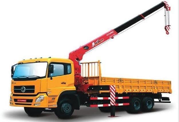
Logistics are the key to successful implementation of any large-scale construction or industrial project. In particular, it relies on safe and timely heavy lifting exercises. Experienced project managers understand that one should choose the lifting partner. This choice steps well beyond the scope of checking a daily rental rate. It involves serious technical and operational due diligence. Searching for crane hire near me starts a critical selection process. This instructive paper provides a professional guideline of checking local vendors. It guarantees that your decision will have the high standards of contemporary engineering. You need someone with whom to share your working environment. Such a partner should provide a smooth component of your project timeline. Determining which crane gets hired out of the most competent ones would require examination. This includes the analysis of their safety culture and history of equipment maintenance. It also needs to examine their local regulatory compliance history. An informal method will cause expensive time wastage and loss of safety. That is why it needs to have a systematic, professional ideology in its vetting procedure. Choosing the best crane hire near me establishes project resilience. You require an established local know-how and quick reactivity. This choice is a difference in your budget, time and reputation. Reputable crane companies provide more than just machinery. They provide expertise and human resources. Act with accuracy to ensure that the project is successful. The Strategic Advantage of Localized Crane Hire Near Me Close quarters have crucial, measurable benefits of the project. Opting for local crane hire near me is a strategic decision. It is not merely an issue of convenience or routine preference. Local knowledge directly converts into efficiency and reliability in operation. The best crane rental companies offer deep regional insight. Such experience assists in anticipating the countermeasures to the typical local problems. It is important to know the particular operating environment in order to be successful. Local suppliers are well versed with conditions in the ground. They are aware of the peculiar weather patterns in terms of timing. They are also aware of the local particularities of logistical limitations. The familiarity saves time, which is used to visit the site and plan. Therefore, localized crane hire near me shortens lead times significantly. It helps in creating a project set up which is much smoother and faster. Regional Regulations and Permitting Expertise The heavy lifting has special challenges for the local bureaucracy. There is a great deal of variation in regulations of road permits and lifting plans. They tend to vary according to the jurisdiction or a regional authority. A trusted local partner specializing in crane hire near me is vital. They will have fruitful liaisons with local regulators. This knowledge not only makes the whole process of permitting easier and faster. Professional management of paperwork eliminates expenses on litigation. The best crane companies maintain current knowledge of all local codes. They check all lifting plans to ensure that they are compliant. These involve the observation of given height limitations or traffic regulations. His and her reliability and trustworthiness is demonstrated by their compliance history. Hence, the selection of a locally-based company reduces the chances of exposure to the regulatory risk. Reducing Mobilization Costs and Downtime Costs of the transportation of equipment are high. The mobilization at long distances is highly inflammatory to the project budgets. It also creates unjustified logistical complications and risks. Choosing a crane hire near me partner minimizes these transport expenses. It reduces the number of wear and tear posed by the long hauls. The adjacency also makes the jobs have faster turnaround times. Shorter travel period will be associated with increased adherence to the schedule. In case of any unforeseen failures, the process of its repair is rapid in the area. The nearby crane companies are able to bring the replacement parts at a short time. They are also able to send a replacement machine speedily. This rapid response will reduce the loss of time of projects. This is an effective strategic decision that increases the efficiency of the projects. Vetting the Fleet: Matching the Machine to the Mission The scope and condition of a company’s fleet reflect their capability. When seeking crane for hire near me, the focus must be on suitability. You must critically assess the provider’s heavy-duty equipment. The provider must perfectly match the machinery to the project’s specific demands. Over-specifying equipment wastes capital resources unnecessarily. Under-specifying equipment introduces unacceptable safety hazards. You must meticulously review the load charts and specifications. Confirm the crane’s capacity meets or exceeds your lifting needs. Assess the required boom length and operating radius carefully. Inquire about the average age and maintenance cycle of their cranes. The best crane rental companies provide transparent service logs. High fleet quality is non-negotiable for project security. Assessing Technical Specifications and Safety Profiles The technical profile of a crane determines its working limit. It is of great importance to know ground pressure demand. You have to determine the requirements in outrigger arrangement and the position of counterweight. The provider should have the ability to prove that they have a well-understood understanding of their equipment. Search Digital fleet management systems that are detailed on tracking. These systems validate frequent and active maintenance systems. The equipment has to be made safe. The new cranes have sophisticated electronic safety systems. These are load moment indicators and anti two block systems. Verify that the crane hire near my provider’s fleet is up-to-date. Make sure that they have lifting accessories of high quality and non compromised. Safety prioritization is manifested through commitment to technical excellence. The Efficiency of a Crane Truck for Hire Near Me Small scale lifts and quick deployment: In this case, consider specialized vehicles. A crane truck for hire near me offers unique flexibility. These all purpose units are both transporting as well as lifting. They are best suited to tasks that need to be done within a day or are in a congested area. Their installation and dismantling times are very
Benefits and Applications of Mini Crane Hire for Restricted Access Projects
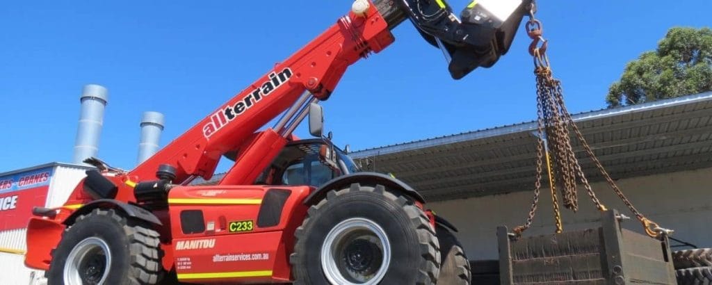
The world of construction and engineering is ever changing. The contemporary projects often require performance in a very hostile environment. These environments carry with them previous building footprint and intensely urbanized areas. The classic lifting equipment is usually not effective in these areas. That is why more specific and adaptable options should be sought out by the professionals. The strategic use of mini crane hire has become a vital component for success. It provides a clear answer to this never-ending access problem. This detailed analysis explores the substantial benefits of utilizing mini crane hire. It also looks at the specialized uses that can be best relating with these machines. The benefits of these small lifters will be dissected into the benefits their operations give to their operations and economics. Moreover, we will determine the reasons as to why they are critical lifting instruments in the current century. Embracing mini crane hire ensures projects proceed efficiently and safely. The approach is very important in ensuring project schedules. Navigating the Challenges of Confined Spaces with Mini Crane Hire Footprints in construction sites are becoming smaller in urban centers full with people. This trend poses some major logistical challenges to the project managers and engineers. The transportation of heavy equipment and materials is complicated and even impossible. Ordinary mobile cranes are not able to reach small alleyways or inside areas. It is this inherent limitation that determines a novel way of project implementation. Mini crane hire provides the necessary maneuverability and power. The Operational Conundrum of Limited Access Logistics planning involves consideration of access points. Most of the projects entail heavy weight to be lifted to the internal courtyards or rooftops. Normal cranes require huge set up areas and wide tail swing areas. All these needs are not easily achieved in the developed infrastructure. The scarcity of space highly exaggerates the project complexity, and the cost. Moreover, it brings a lot of delays in the construction process. Mini crane hire resolves these spatial conflicts completely. The difficulty does not end with the spatial limitation. It entails maneuvering mass weight restrictions on internal floors or sensitive ground-situations. Existing structural elements are very easily damaged by heavy machinery. This risk introduces potential structural failure concerns. Precision is non-negotiable when operating near high-value assets. Mini crane hire units are designed to address these sensitive site conditions. Why Traditional Cranes Fail in Urban Environments Big cranes are really huge with immense lifting power and capacity. Nonetheless, their size is too large to fit on most contemporary jobs. It is time consuming to erect and dismantle such huge machines. This is the process that will require significant effort and various resources. This has resulted in a very narrow margin of heavy lifting. This is a limitation that directly impacts the efficiency of the project. Conventional cranes are based on ground requirements that enable the huge stabilizing pressure. This implies that they usually require massive site preparation and expensive strengthening of the site. Moreover, extra drivers and unpleasant escorts are needed on the way to navigate in the city traffic. This supply chain nightmare introduces a non-productive overhead of enormous proportions. Mini crane hire options mitigate these infrastructural and regulatory barriers successfully. They provide a noncomplicated yet strong alternative. Defining the Compact Advantage of Spider Crane Hire The basis of their value propositions is the small size of these specialized cranes. People often refer to them as spider crane hire due to their unique outrigger system. They use these adoptable legs in difficult and rough grounds. The given peculiarity enables them to stand in narrow areas and inclinations. When packed and shipped away, they occupy a terribly small footprint. A spider crane hire unit can pass through a standard doorway or service elevator easily. This exceptional ability allows reaching hitherto closed interiors. When they are inside of it they unfold to give an impressive lifting power. This two-purpose is essential in the internal fit-outs and repairs. Its extremely fined controls also ensure accurate and easy placement. This saves much in terms of installation time and effort. Core Benefits of Choosing Small Crane Rental for Precision Lifting Selecting small crane rental provides a strategic advantage in competitive markets. It goes further than being accessible to provide the fundamental operational benefits. Manufacturers construct these units to offer high performance and serviceable services. They provide a combination of power, precision and speed which the large cranes are incapable of. This flexibility will directly translate into improved project delivery. Unmatched Versatility and Agility These cranes are not single-purpose machines; they boast incredible versatility. They can handle a vast range of lifting tasks across various sectors. The inherent agility of a small crane hire makes it suitable for quick repositioning. Operators can move the crane between tasks rapidly and efficiently. This minimizes downtime and maximizes the productivity of the equipment. Their design allows for operation in extremely low head-room environments. This is a common constraint in plant rooms and existing building spaces. The telescopic boom allows for precise, horizontal movements. This is often necessary for navigating complex internal structures. Utilizing small crane hire ensures that no lifting requirement is too intricate or challenging. This agility is a key competitive differentiator. Enhanced Safety Protocols and Load Stability The issue of safety is the most critical matter in any complicated work place. The mini crane hire unit’s stability system is technologically modern. Their interlocking outriggers observe the pressure and load moment on the ground. This closed feedback control allows harmful overloads or tip-overs to be avoided. These features instill confidence and safety in the operators and the general safety of the site. Furthermore, remote control operation that entails mini crane hire would greatly enhance the safety. The operators are able to place themselves at the best vantage point. This enables them to stay at a long distance from the suspended load. Their visibility of the lift pathway and other labourers is clear. Mini crane hire is investing in a better safety culture. The option minimizes
When and Why You Need a Heavy-Duty 50 Ton Crane Rental for Major Construction
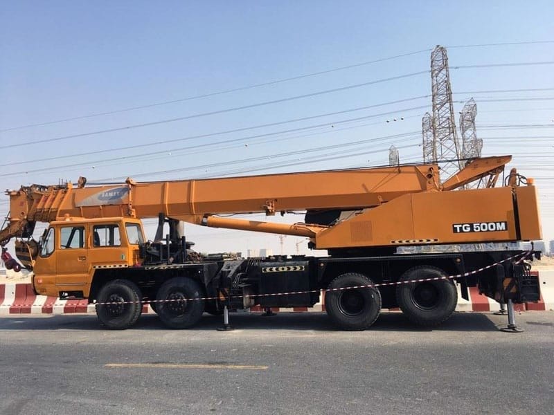
The crane used is heavy-duty. It requires a strict examination of project scope and location restrictions. The appropriate lifting capacity is important in terms of optimal logistics. This is a process that is not merely about the counts of weights. It entails the study of the active forces involved when lifting. For many mid-to-large-scale endeavors, the sweet spot often lies with a 50 ton crane rental. The ability provides the ideal power-to-precision-to-mobility solution. It is a labor intensive feature that is fundamental in the development of modern infrastructure. Defining the Strategic Value of a 50 ton crane rental The size of a unit of 50 tons expresses a pioneering strength in the building sector. This type of mobile crane is very versatile and powerless. It gives considerable lifting power but at the floorprint of bigger sizes. Project managers frequently turn to a 50 ton crane rental for versatility. Such machines address all the lifting operations that are of high criticality. They are also part and parcel of vertical and horizontal construction stages. It is now time we will look at the details of situations that support this investment. When Load Requirements Demand a Robust $50$ Ton Solution Numerous structural elements fall within the exact range of lifting. According to the example of big precast concrete commercial building panels. Another typical task is lifting heavy steel trusses to make the structure sound. This capacity is also needed in the installation of complex mechanical equipment. Large HVAC units, chillers and generators will tend to be over smaller crane capacity. A 50 ton crane rental is perfectly suited for these heavy placements. Its capacity will make sure that the desired level of safety is always guaranteed. The amount of suspended load to be obtained is important to determine correctly. This gross weight should comprise of all the rigging accessories and hook block. The 50 ton crane rental must safely handle this entire system weight. Meanwhile bear in mind that the maximum capacity decreases remarkably with the working radius. Capacity-limited lifts Long outreach lifts are nearly always limited. The exact load chart of the crane should always be checked to retrieve the lift configuration. Addressing Vertical Reach and Radius Challenges The top and access requirement of a project are some of the major decision motivations. These cranes on wheels are very successful in medium height construction works. A typical 50 ton crane rental can reach impressive tip heights. This range is appropriate to the multi-story commercial or mid-rise residential buildings. The telescopic boom has the feature to adjust height and angle very fast. This is a considerable advantage over conventional lifting systems. It also wastes no value in time-saving during dynamic building schedules. The distance, or the radius, which is horizontal, is no less significant than the height. Relocating the materials that are distant to the crane will need serious counterweight. A 50 ton crane rental manages challenging radius demands effectively. Falling outside the rated radius limit can however be disastrous. Accurate planning eliminates risk and compliance of safety of the site. This is the reason why they are suitable in the infrastructure work that includes bridge construction. Logistical and Operational Superiority of Mobile Cranes Mobility is the key in the busy world of a large construction site. Mobile cranes particularly truck-mounted or all terrains are essential. They are highly flexible when compared to permanent installations. This is enabled by quick mobilization that promotes project speed. It makes the 50 ton crane rental a highly strategic asset. Quick Deployment and Site Accessibility Mobile cranes actually cut the time needed to set up down by a great margin. Workers may push them onto the field regularly and install them within a few hours. This is very different to the assembly required by other solutions. The outrigger setup only needs minimal preparation of the site. Their moderately small sizes enable them to reach confined locations in the cities. This comprises functionalities of minimal space in compounds. A 50 ton crane rental is thus optimal for fast-paced, multi-phase projects. Mobility Across Large or Multiple Work Sites One key benefit is the ability to move the crane efficiently. It can service different lifting needs across a sprawling campus. It can also relocate between entirely separate projects quickly. Initial planning often overlooks this operational agility. This flexible asset use greatly enhances project efficiency. The ability to relocate saves substantial time and costs. Fixed lifting systems cannot possibly offer this. Tower Crane Hire vs. 50 ton crane rental: The Decision Matrix Choosing between a mobile crane and a fixed system is a strategic decision. Both options have distinct strengths and weaknesses. The choice must align perfectly with project duration and scale. Understanding this matrix is key to achieving efficiency and budget adherence. We must compare the suitability of each option in detail. Height, Duration, and Frequency Considerations Tower crane rental is the uncontested champion for vertical height. These are necessitated in constructions that are more than seven or eight stories. They involve the continuous monolithic lifting at colossal heights. Their requirement is, however, a long term commitment, and foundation. A 50 ton crane rental is better for short- to medium-term projects. It handles lower-rise lifts that are not repetitive and it is very efficient. It is this flexibility that suits well with the projects that have diverse lifting schedules. Setup Costs and Environmental Impact Setting up a tower crane that is fixed is a time-consuming and costly undertaking. It involves special set up and subsequent deconstructions. A 50 ton crane rental offers a lower total cost of mobilization. How disruptive the operational impact is also is much less. It does not require huge concrete foundations or anchors. This is an invaluable reduction of footprint in densely populated urban areas. This cost benefit analysis may be inclined towards the mobile option in most cases. Technical Due Diligence for 50 ton crane rental The successful use of a construction crane rental hinges on planning. Due diligence does not just end at
Your 7-Point Checklist for Unbreakable BMS Security and Facility Protection

Modern commercial and industrial facilities rely on interconnected systems that control everything, such as climate and access points. However, this connectivity creates vulnerabilities. BMS security is a critical priority for facility managers and engineers who recognize that their building automation infrastructure represents both an operational asset and a potential liability. The convergence of operational technology with information technology has fundamentally changed how we must approach building management system security, requiring a comprehensive strategy that addresses technical, procedural, and human factors. Whereas there was a closed-loop system which was working in isolation, it now integrates with enterprise networks, cloud-based systems, and mobile devices thus the attack surface becomes vast. The fact is that attackers find building systems more and more interesting targets, both in terms of monetary benefits or their destruction or as espionage. A compromised building management system can lead to equipment damage, compromised occupant safety, operational disruption, and significant financial losses. It is no longer an option to know about the threat and establish effective protection. It is essential to good facility management. Understanding the Threat Landscape in Building Automation The threats facing building automation security have evolved dramatically. This is because these systems have become more sophisticated and interconnected. A building system ransomware can lock out facility managers from critical controls. This results in emergency cases that demand urgent payment. Numerous incidents occur because of industrial control system malware worldwide. These aren’t theoretical concerns but documented realities that have affected organizations across various sectors. There are significant differences in the motives of attacks. There are people whose sole interest is financial benefits through ransomware or data theft. Others just want to disrupt the system and prove its vulnerability. State sponsors can act strategically by attacking critical infrastructure, whereas aggrieved insiders may use their privileges to cause damage. All threat actors come with various defining capabilities and persistent levels, necessitating defensive approaches that respond to many things at the same time. Modern building systems are linked and interconnected. This means that an open door in one system can destruct the whole infrastructure. Common Vulnerabilities in Building Management Systems Many building management system cyber security weaknesses stem from legacy design assumptions that never anticipated network connectivity or remote access. Older systems were engineered with operational reliability as the primary concern. They operated on the premise that physical security would prevent unauthorized access. This approach made sense when controllers operated on isolated networks within locked equipment rooms, but it creates substantial risks when these systems connect to enterprise networks or the internet. Default credentials remain one of the most exploited vulnerabilities in building automation security. Manufacturers ship equipment with standard usernames and passwords intended for initial configuration. However, facility teams often fail to change these credentials during deployment. Attackers maintain databases of default credentials and can gain access within minutes of identifying vulnerable systems. The problem compounds when vendors use the same default credentials across entire product lines, meaning a single compromised password can unlock thousands of installations. Network Architecture Weaknesses Flat network architectures where building management system components share network segments with general business systems create unnecessary risk exposure. At least with building control systems direct access by a hacker who has compromised a workstation on the corporate network is possible without proper segmentation. Most structures were automated in their buildings prior to the emergence of cybersecurity as a key priority and hence have a design that emphasizes comfort over safety. Retrofitting appropriate network segmentation gives the network much needed protection over time against even cross- network by enemies, but it must be properly planned. Unencrypted communication protocols send sensitive data and control instructions in clear text and this enables the attacker to have access to network transmissions and Volumetric data and inject malicious commands using such transmissions. Numerous industrial standards were created long before encryption became a norm and switching to secure versions places a burden on equipment upgrades as well as compatibility testing. This problem becomes more complicated in a mixed environment where older and newer systems have to coexist. Implementing Comprehensive BMS Security Measures Effective building management system security requires a layered defense strategy that addresses multiple vectors simultaneously. There is no one control that is utterly protective but a combination of the technical controls, procedural controls and human awareness forms strong controls. This is based on the foundation of network segmentation which prevents the association of building automation systems with basic business networks and the internet. Such segmentation must be based on a hierarchical design with each field devices, control systems and management interfaces being placed into different security zones with restricted communication pathways between them. Firewall policies that regulate inter-zone communications ought to be based on a deny-all policy, which clearly allows only the required flows of traffic. Such a tightened position allows the detection of possible links to products of unforeseen interference or improper setting. Network access control systems can enforce device authentication requirements, preventing unauthorized equipment from connecting to building automation security networks. Virtual private networks are beneficial in that they ensure remote access by authorized personnel and a high level of authentication and encryption measures that keep credentials and content of communication safe. Authentication and Access Control Strong authentication mechanisms form a critical component of BMS security strategies. All remote access and their privileged local access should be required to use multi-factor authentication where the user must provide something they know, something they bear and they may be. This will significantly minimize the chances of lost credentials that may result in unauthorised access. Role based access control systems mean that required personnel will only have access to functions that they need to fulfill their duties and cannot cause much harm because of compromised accounts or insider threat. Regular credential rotation policies force periodic password changes and eliminate service accounts with permanent static passwords. Automated credential management systems can generate, distribute, and rotate passwords without requiring manual intervention, reducing administrative burden while improving security. Session management controls should enforce timeouts for idle
Everything You Need to Know About BMS System Course

The building automation business is booming at an unprecedented rate. The demand for knowledgeable specialists is on the rise. A BMS system course has become an essential stepping stone for engineers, technicians, and facility managers looking to advance their careers in this dynamic field. Whether you’re a seasoned professional or just starting out, understanding the value and scope of BMS training can open doors to lucrative opportunities across East Africa and beyond. Automation is not anymore a luxury but it is a necessity in the present-day energy-sensitive world. Commercial and industrial facilities as well as residential complexes and buildings become dependent on the use of more complex forms of control to maximize energy consumption, increase comfort, and efficiency of operation. This change has brought about a desperate demand of qualified individuals who comprehend the complexities of them. A comprehensive BMS system course provides the technical foundation and practical expertise required to meet this demand. It is not whether or not you should have this training, but how soon can you begin to avail yourself of what is shaping up to be a huge opportunity in the construction and facility management market sector of Kenya, Uganda, and Tanzania. Understanding the Core Components of a BMS System Course When you enroll in a quality building management system course, you’re not just learning software interfaces or hardware specifications. You are having a systems-level view of the functioning of modern buildings as eco-systems. You study about system architecture, strategies of control, communication standards and principles of energy management. The majority of programs start with a simple background. Here you get to know about sensors and actuators. You learn about how these devices interact to provide intelligent building settings. The training then moves to more advanced issues like the use of HVAC, control over lighting, the coordination of security systems and management of the fire safety systems. A well-structured BMS system course emphasizes hands-on experience with industry-standard platforms and technologies. You will operate the real controllers, code real sequences and solve the real problems arising in the systems. This practical approach ensures that when you complete your BMS training, you’re not just theoretically knowledgeable but genuinely capable of implementing solutions in real-world scenarios. The most effective programs feature the case study of real projects. Through this, you can learn the successes and failures in the industry. Moreover, you learn about new technologies in the building management system space. These include IoT integration, cloud-based solutions, and the use of artificial intelligence in building automation process. Essential Skills Developed Through BMS Training The knowledge you gain with a good BMS system training is far much deeper than the mere operation of the system. To begin with, you become a technical expert when it comes to programming and programing the BMS controllers based on the industry standards like BACnet and Modbus and LonWorks. They are the basis of the modern building automation and their knowledge is paramount in system integration and troubleshooting. You will be taught to write control sequences in various equipment such as air handling unit, fan coil unit, chillers, boilers and variable air volume system. Beyond technical skills, a quality building management system course cultivates critical thinking and problem-solving abilities. Automation systems are not that easy to develop, and the problems cannot be easy to fix. By the end of your training, you will be able to think analytically to identify problems in a systematic way without you competing with your competitors in a hardware or software issue, a disconnected network, or a inappropriate control logic. You will also be able to project manage, learn how to plan your installations, how to liaise with other trades, to commission your work correctly and how to document your work in a professional manner. Furthermore, modern BMS training emphasizes energy analysis and optimization techniques, teaching you how to leverage system data to identify savings opportunities and improve building performance continuously. Career Pathways After Completing Your BMS System Course Completing a comprehensive BMS system course opens multiple career trajectories in the building automation industry. The lowest level of positions is that of BMS operator whereby you would monitor the systems through the control rooms, provide responses to alarms and ensure operational shifts. With the experience, you may advance to the BMS technician jobs whereby you are required to work with the field devices, controllers and troubleshooting equipment. The roles are usually well-paid and offer good chances to acquire practical experience in different types of buildings and different construction of the system. And with further experience and more training in building management system, you can become a BMS engineer or design engineer. These functions include establishment of the system architectures, development of control strategies, preparation of specifications and complex projects through the entire commissioning process. It is common to find that many of these professionals become specialized following some years in specific fields like energy management, system integration or through consultancy services. East African market especially attaches a lot of importance to professionals who can integrate technical knowledge of BMS with the knowledge of local building code, climatic concerns, and local project demands. Senior BMS training graduates often become project coordinators, automation specialists, or smart building consultants, commanding premium salaries while working on landmark developments across Kenya, Uganda, and Tanzania. Selecting the Right BMS System Course for Your Needs Choosing the appropriate BMS system course requires careful consideration of your current skill level, career objectives, and learning preferences. When you are totally new to automation construction training, you need to seek entry-level courses that will begin with elementary electrical and control information and then move to BMS oriented information. These introductory building management system courses typically run six to eight weeks and provide comprehensive coverage from fundamentals through intermediate topics. They would be perfect in the case of HVAC technicians, electrical engineers, or facility managers shifting to automation jobs. For experienced professionals seeking to deepen their expertise, advanced BMS training programs focus on programming, system integration, and energy optimization
Why an Advanced BMS Data Center Solution is Your Only Option for 100% Uptime
If you run mission-critical operations, then you know that the infrastructure must never falter. Facilities where any single downtime can result in millions of losses and damaged reputation require reliable systems in place. These systems help monitor, control, and optimize every process behind the scenes. We are talking about a robust BMS data center. A data center BMS represents the central nervous system of your facility. It controls cooling and power distribution, security and environmental controls. Unlike traditional building management approaches, implementing a data center BMS system addresses the unique challenges of environments where temperature fluctuations of even a few degrees can trigger equipment failures, where power interruptions are simply not an option, and where security breaches carry consequences that extend far beyond the physical facility. Understanding the Core Functions of BMS in Data Center Operations The foundation of any effective BMS data center lies in its ability to provide comprehensive oversight across multiple critical systems simultaneously. These are not single monitoring areas placed all over in your facility. Instead, a sophisticated data center BMS creates an integrated ecosystem where every component communicates, responds, and adapts in real-time to changing conditions. The basic functionality of a BMS in a data center setting is to regulate five areas. The first is the environmental control. Here the system provides improvements in temperature and humidity levels necessary for IT equipment. The second are is power managing that offers effective distribution and redundancy of your infrastructure. The third area is the security systems that integrates access control, surveillance, and intrusion detection on a single platform. Fourth, automated responses respond to all cooling load changes as well as the use of backup systems in case of anomalies. Fifth, complex data analytics use unprocessed sensor data to create value (statistical insights) to spur continuous improvement. Real-Time Environmental Monitoring Temperature management in a data center BMS system goes far beyond simple thermostat control. The sophisticated sensors at every part of the server rooms, cooling units and airflow routes generate finer thermal maps. The building management system data center platform processes this information continuously. The system: The humidity management is operated in parallel and is able to keep humidity at a level that does not generate condensation damage as well as eliminating the build up of static electricity which may harm delicate electronics. Power Infrastructure Optimization Power has not only become the blood of life but also the biggest production cost in most of the facilities. A properly configured data center BMS tracks consumption at granular levels, from individual racks to entire power distribution units. This visibility allows load balancing by ensuring that no one circuit is congested and the amount of unused capacity is exploited. In case, the utility power supply resorts to failure, the BMS used in data center operation initiates the shift over to uninterruptible power supply and generators and rejects failover chains that ensure uninterrupted process, without operator input. Integrated Security Architecture Physical security in a data center BMS system extends beyond traditional access control. Contemporary implementations associate badge access information with surveillance videos, environmental devices and even network activity logs. When someone enters a restricted area, the BMS data center platform verifies authorization, records the event with timestamp and video evidence, and monitors for unusual patterns that might indicate social engineering attempts or compromised credentials. The security layers resulting through this integration counter the aspects of the appearance of new threats as well as the undisrupted access that authorized personnel need. Critical Components That Make BMS Data Center Systems Effective Building an effective data center requires specific hardware and software components working in concert. The central management station is the command center, however, its efficiency solely depends on the quality and position of field devices, the quality of communication networks, and the complexity of control algorithms. Sensor Networks and Data Collection A comprehensive BMS in data center installations typically deploys hundreds or even thousands of sensors. Each server rack has temperature probes that check the air temperature both at intake and exhaust points. Moisture sensors monitor the humidity in the facility. The power meters measure power usage, voltage, and current at distribution points. The airflow sensors maintain that the cooling systems produce the right volumes of cooling air to the heat generating equipment. Physical access is monitored using door contacts and motion detectors. The data center system aggregates this constant stream of data, filtering noise, identifying trends, and flagging anomalies that demand attention. Control Systems and Automation Logic Raw data are only of value upon an act. Modern building management system data center platforms employ sophisticated control algorithms that respond to multiple variables simultaneously. In case load on a server surges during business peak hours, the system does not simply pump on the cooling everywhere. Rather, it considers what areas need extra cooling, or can adjust the variable speed fans to achieve accurate volumes of airflow, or can adjust chiller output to match demand, and can even liaise with the power management systems to provide the extra electrical capacity needed by the increased cooling requirements. User Interfaces and Reporting Tools Even the most sophisticated data center BMS proves useless if operators cannot access its capabilities effectively. The modern systems offer an array of interface choices, based on particular role and situation. The operators of routine operations can view dashboard displays of the real time status of all systems and the clear visual pointers pointing at the areas of concern. Facility managers who assess performance trends investigate the history of data using customizable reports that trace the energy efficiency, equipment usage, and maintenance needs, as well as capacity usage. In the incidents, the emergency responders should have user-friendly interfaces that will provide the critical information without reverting to exhaustive details so that they can take swift judgment and make decisions Assessment and Design Phase Every effective data center BMS system implementation begins with comprehensive facility assessment. Engineers evaluate existing infrastructure, identifying critical systems, potential failure points, and opportunities for improved efficiency. This assessment